1 finite element model of the rotor system 1.1 Simplification of 5 watt tilting pad bearings The oil film dynamic characteristics of the sliding bearing reflect the corresponding change of the oil film force when the journal deviates from the static equilibrium position and moves near this position, and usually plays the role of nonlinear elastic force and damping force. However, in most cases, the oil film force can usually be reduced to a linear elastic force and a damping force because only a small amplitude is involved. Large centrifugal compressor rotor systems use 5 watts of tilting pad bearings. 1.2 Simplification of the diaphragm coupling In the bending vibration analysis, the bending stiffness of the coupling must be considered, so it is necessary to simplify the necessary according to its actual size. The mass and the moment of inertia do not change. When the coupling is matched with the shaft, it is simplified to a solid shaft. 1.3 rotor system finite element model This article uses beam elements to simulate the shaft. Considering that the axial deformation in the actual rotor system is small relative to the bending deformation and torsional deformation, it can be neglected. Therefore, the displacement of the joint nodes is regarded as the generalized coordinate of the beam element. Considering the effects of the diaphragm coupling and the 5 watt tilting pad bearing, a finite element model of the rotor bearing system is established. 2 unbalanced response analysis The position and size of the unbalanced amount of each cylinder rotor system according to the relevant design criteria. 3 unbalanced response simulation of the system under different bearing parameters In the case of different length-to-diameter ratios (L/D=0.5, 0.7, 1.0), calculate the horizontal and vertical composite amplitudes of the journals at the left bearing of the low-pressure cylinder as a function of the rotational speed, as the aspect ratio increases. When passing the critical speed, the resonance peak will decrease, and the amplitude will be 5.58, 5.16, and 4.59m respectively near the operating speed. The large aspect ratio is beneficial to reduce the journal vibration. However, considering the large aspect ratio, it is easy to cause oil drainage difficulties, which may cause the oil temperature to rise, which is not conducive to stable operation of the rotor. If the length-to-diameter ratio is chosen to be 0.5, the vibration will be excessive when the formant is over-exposed. Therefore, for the system to meet the design requirements, the selected aspect ratio is 0.7. Take L/D=0.7, and the other parameters are the same as in Figure 5. Different gap ratios (cp/R=0.20%, 0.25%, 0.30) In the case of %), calculate the composite amplitude of the journal at the left bearing of the low pressure cylinder with the speed change curve. As the clearance ratio increases, the critical speed will decrease when the critical speed is passed, but the resonance peak will increase. In the working speed range, the amplitudes are 3.19, 4.64, 5.56 m. It can be seen that increasing the gap ratio will cause the critical speed to decrease, the formant to increase and the journal vibration to increase. Take cp/R=0.30. In the case of different lubricant types (32, 46 and 68), calculate the combined amplitude of the journal at the left bearing of the low pressure cylinder with the speed of the different lubricants. Different lubricating oil models have a great influence on the vibration characteristics of the system. The vibration of the system using No. 32 lubricating oil is obviously larger than the other two, while the other two are not much different. The amplitudes in the working speed range are 13.5, 5.56 respectively. , 5.29m. From the above analysis, it can be seen that the lubricating oil with high viscosity is beneficial to reduce the vibration of the journal. For engineering practice, the lubricating oil No. 46 is usually selected. Through the above analysis, it can be found that a large aspect ratio can reduce the formant and reduce the journal vibration; a small gap ratio will cause the critical speed to increase, the formant to decrease, and the journal vibration to be weakened; The viscosity of the lubricating oil can reduce the vibration of the journal. 4 Comparative analysis of experimental and theoretical calculations A large-scale centrifugal compressor is tested on site, and each cylinder is coupled through a coupling. By adjusting the control system, the speed of the speed can be controlled. The position of the vibration test is the left and right bearings of each cylinder. The horizontal and vertical bearings are collected during the acceleration process. Vibration data in the straight direction. The parameters selected for the bearing during the test are: length to diameter ratio L/D = 0.7, clearance ratio cp/R = 0.3%, and lubricant type 46. The low-pressure cylinder left bearing is still taken as an example to compare the theoretical and experimental unbalanced responses in the horizontal and vertical directions. The critical speed is basically the same, but the resonance peaks are quite different. In the working speed range, the amplitude is relatively close, but the actual amplitude is still slightly larger than the calculated value. This may be due to the small basic stiffness of the test vehicle. Or calculate the larger damping selection. 5 Conclusion (1) By studying the influence of different bearing parameters on the journal vibration, it is found that the large aspect ratio can reduce the formant and reduce the journal vibration; the small gap ratio will increase the critical speed, reduce the formant and weaken the shaft. Neck vibration; change the type of lubricating oil, increase the viscosity of the lubricating oil, and reduce the vibration of the journal. (2) Through theoretical comparison and experimental analysis, it is found that the actual journal vibration is slightly larger than the theoretical calculation. Considering the influence of various factors may be due to the small foundation stiffness of the test vehicle, the test vehicle has a gas medium or the calculation damping is larger. To.
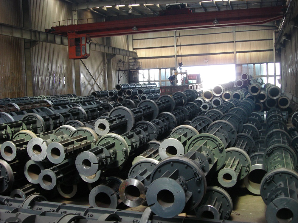
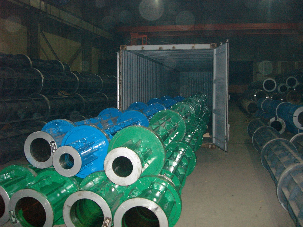
Concrete Pole mould
Length: 6m-18m
Top diameter: 150mm-230mm/by buyer
Taper: 1:75/by buyer
Advantage: high quality, easy operation
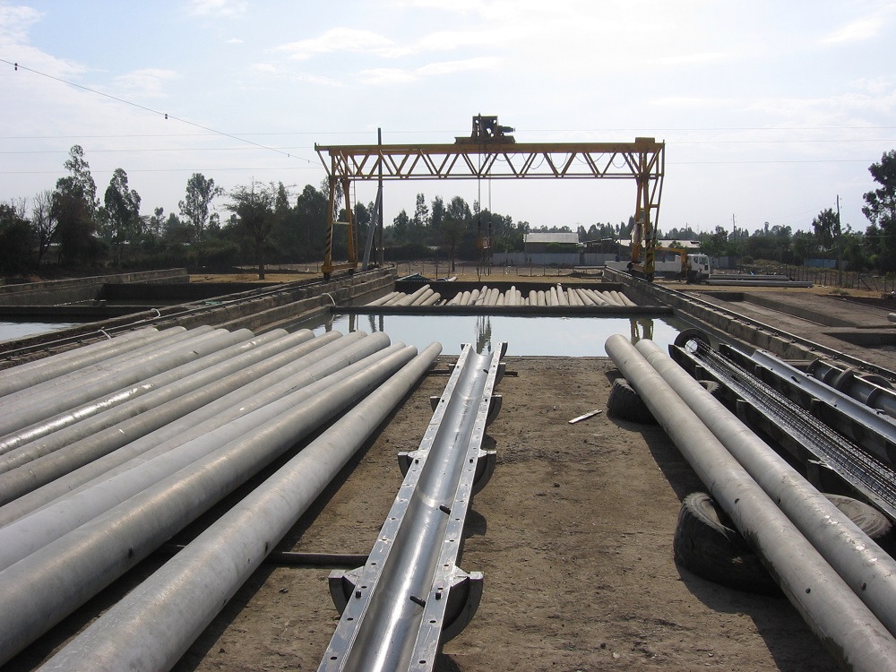
Pre-stressed concrete pole mould is used for electronic concrete pole making. Its mainly manufacture technology is longitudinal tension by steel wires. Then it can squeeze out the excess water in the concrete under the centrifugal force. Thus, it can greatly improve the concrete density and strength.
In order to form concrete more quickly to meet the design strength of more than 70%, steam curing can be carried out so as to shorten the mould-releasing cycle.
Our factory produces two categories of Pre-stressed concrete pole steel moulds, DMZ&DMD. The Pre-stressed Electric Poles by this series equipment comply with the China Standard JC/T364-2001.
Features:
1. Welding technology, which enhances the smooth finish of the mould wall, and eliminates the uneven traces of rivet holes. So the concrete poles appearance will be improved significantly.
2. The cylinder is changed to U-type longitudinal stiffeners which can greatly increase the stiffness and flexural strength of the steel mould,
3. Install the slot with rubber sealing strip, in order to prevent leakage to ensure quality.
The Technical parameter:
Inside Diameter(mm)
Wheel Distance(mm)
Wheel Diameter (mm)
Length(mm)
Ø100
2000
Ø600
6-7
Ø110
2000
Ø600
6-7
Ø120
2000
Ø600
6-8
Ø130
2000
Ø600
6-8
Ø150
2000
Ø600
6-10
Ø170
2000
Ø600
6-12
Ø190
2000
Ø600
7-12
Ø190
2000
Ø650
15-18
Ø230
2000
Ø650
6-9
Ø310
2000
Ø650
6-9
Ø350
2000
Ø680
6-9
Ø390
2000
Ø750
6-9
Centrifugal Machine,Spun Prestressed Pole Mould ,Spc Pole Mould,Spc Pole Mould In Bangladesh Jiangsu Haiheng Building-Materials Machinery Co.,Ltd , https://www.jshaiheng.com


